 |
|
 09-24-2022, 06:35 PM
|
#61
|
4 Rivet Member 
1949 22' Liner
1969 27' Overlander
1969 27' Overlander
Walnut Creek
, California
Join Date: Apr 2015
Posts: 325
|
Quote:
Originally Posted by Aerowood

One other thing to consider is running all of the DC grounds to a common DC ground buss. More work but more reliable. My DC grounds all go to the same buss, including the exterior lights.
Sent from my Lenovo YT3-X90F using Airstream Forums mobile app |
Yep! Just like on a boat. I aim for zero current on the skin. Single point grounding is right. Less risk of electrolysis that way.
|

|

|


|
09-24-2022, 07:42 PM
|
#62
|
Rivet Master 
2022 27' Globetrotter
DALLAS
, TX
Join Date: Apr 2022
Posts: 1,497
|
Quote:
Originally Posted by Jcondon
Yep! Just like on a boat. I aim for zero current on the skin. Single point grounding is right. Less risk of electrolysis that way.
|
Yup. Just assume that the trailer is 100% fiberglass and is therefore non-conductive. In that scenario, all power wiring must use pairs of wires and must also have a single common connection for all of the negative terminals (I hesitate to call these "ground" connections). In Electrical Engineering terms, a better label would be "common voltage reference point".
|
|
|
|
|
09-24-2022, 07:56 PM
|
#63
|
4 Rivet Member
1949 22' Liner
1969 27' Overlander
1969 27' Overlander
Walnut Creek
, California
Join Date: Apr 2015
Posts: 325
|
Quote:
Originally Posted by foobar
Yup. Just assume that the trailer is 100% fiberglass and is therefore non-conductive. In that scenario, all power wiring must use pairs of wires and must also have a single common connection for all of the negative terminals (I hesitate to call these "ground" connections). In Electrical Engineering terms, a better label would be "common voltage reference point".
|
I call all common voltage reference point wires Negative, and the bonding wire to the shell the ground bond. This can also be the same point for the shore power ground. I like multiple bonds to that single ground point. This keeps everything at the same potential.
|
|
|
|
|
09-24-2022, 08:02 PM
|
#64
|
4 Rivet Member
1949 22' Liner
1969 27' Overlander
1969 27' Overlander
Walnut Creek
, California
Join Date: Apr 2015
Posts: 325
|
Quote:
Originally Posted by foobar
Yup. Just assume that the trailer is 100% fiberglass and is therefore non-conductive. In that scenario, all power wiring must use pairs of wires and must also have a single common connection for all of the negative terminals (I hesitate to call these "ground" connections). In Electrical Engineering terms, a better label would be "common voltage reference point".
|
In this photo the large negative buss is bonded to the enclosure and it would be bonded to the frame and shell. This is not to carry current but as a bond. The insulated negative bar above it would gather all of the negative conductors and the current would be directed to the grounded negative buss. This is the way we wire aluminum boats except we have no motor. 
|
|
|
|
|
09-24-2022, 08:17 PM
|
#65
|
Rivet Master
2022 27' Globetrotter
DALLAS
, TX
Join Date: Apr 2022
Posts: 1,497
|
Quote:
Originally Posted by Jcondon
I call all common voltage reference point wires Negative, and the bonding wire to the shell the ground bond. This can also be the same point for the shore power ground. I like multiple bonds to that single ground point. This keeps everything at the same potential.
|
Exactly. We are thinking of the same concept, just using different terminology.
Your example is like how a house should be wired here in the USA. Generally speaking the 120v neutral wires are all connected to a common location in the electrical panel. The common neutral bus in the breaker panel is connected to earth ground through a single bonding wire to a stake driven deep into the ground.
Trailers, boats, spaceships, etc should be handled the same way as described above. We really don't want stray currents traveling through our trailer shells. All sorts of nasty things can happen such as voltage differences across the shell causing electrical problems with equipment in the trailer, galvanic corrosion, electrical noise, etc.
|
|
|
|
|
09-24-2022, 08:25 PM
|
#66
|
4 Rivet Member
1949 22' Liner
1969 27' Overlander
1969 27' Overlander
Walnut Creek
, California
Join Date: Apr 2015
Posts: 325
|
Quote:
Originally Posted by foobar
Exactly. We are thinking of the same concept, just using different terminology.
Your example is like how a house should be wired here in the USA. Generally speaking the 120v neutral wires are all connected to a common location in the electrical panel. The common neutral bus in the breaker panel is connected to earth ground through a single bonding wire to a stake driven deep into the ground.
|
This confuses some folks. The neutral is only bonded to ground at one location, The service. All other neutrals are insulated from ground. In our trailers, since the panels are sub-panels, the ground and neutral must never touch. A separate ground bar must be used for grounding. We used to get by with an neutral to ground fault in a house. Now with Arcfault breakers on every circuit if you have a neutral to ground fault, They trip!
|
|
|
|
|
09-25-2022, 01:44 AM
|
#67
|
Rivet Master 
1992 29' Excella
Virginia Beach
, Virginia
Join Date: Jul 2012
Posts: 747
|
Hey there foobar and Richard5933: Im kind of mixing and matching you guys together because the help you are giving me seems to be coming from similar points of view. I read some of the threads that each of you have published, so I know that you both enjoy problem solving and that neither of you are afraid to seek help from others. By addressing you guys collectively I can answer questions once and ask them once. So, I hope you dont mind. 😉
Before I roll into the help you guys are giving me on my stuff I just wanted to tell foobar that I read your last axle thread. I did replace and up size my axles about a year before I began this rebuild about June of 2017. I went from 3500 axles (not Dexter) to I think 4200 Dexter axles with Never lube bearings and self adjusting brakes. Even before I replaced the axles I had already up sized my wheels and tires to 16 with 16" Sendel T03 wheels and Michelin Truck LTX M/S2 225/R75/16" tires. The tires were a nice improvement and the axles even better. I would say we travel pretty light as far as gear in the trailer goes because we used to own a Popup and it did not hold much extra weight. We learned lessons the hard way while towing it. As for the Airstream, with our old axles (which were supposedly less than 10 years old) and the 15 wheels with ST tires we had a serious blow out and lost both tires on the curbside and incurred body damage, all in one incident. Next after up sizing the wheels we had the bearing fail on two different wheels in the span of a few months all within four to five months of repacking the bearings. After those experiences Never Lube bearings seemed like a good upgrade. After I up sized the axles I felt that the trailer towed even better than before.
Richard, I read your stabilizer thread to the end and did not see a conclusion, but I thought your idea of drilling out and installing some nylon or similar plastic blocks to secure the ends of the leveling screws was a really good idea. What did you end up doing?
Moving on:
Quote:
Originally Posted by foobar
You can definitely make a 24v system work. It is just a bit more complicated and costs a bit more to implement. Also, there are fewer native 24v appliances and equipment as well.
|
Quote:
Originally Posted by foobar
A very high capacity (e.g. Expensive) 24 to 12v DC-DC is likely to be needed if you want to supply every 12v item from a 24v battery bank using a single 24 to 12v converter. Example: Tongue jacks, stabilizers, etc. pull quite a bit of current when they are running. If you add up the total number of 12v system amps that you might draw worst case, it is likely to be a pretty big number. Alternatively, you can distribute 24v in the trailer and have smaller 24 - 12v converters near various subsystems. This too can become awkward and expensive with many points of potential failure.
|
Quote:
Originally Posted by richard5933
24 vs 12??? The big deciding factor when I installed the Multiplus II in my coach was how much I was going to use my inverter, and how much I was going to power from it. Resistance (or lack of it) is what the decision revolves around to me.
|
Quote:
Originally Posted by richard5933
If you're planning on running your inverter in the upper portions of its rated capacity often or for longer periods of time, then it makes sense to go with a 24v inverter. Another deciding factor will be the proximity of the inverter to the batteries. If you need to put the batteries more than a few feet (2-3) from the inverter, it starts to make more sense to use the 24v inverter. Longer conductors and/or higher loads make the resistance of your cable more important, and a 24v system has the advantage here. If you're putting the inverter immediately next to the batteries, there is limited advantage to using a 24v inverter other than the weight savings of the cable between them (which can be somewhat substantial if near the tongue).
A high-quality step-down converter can easily power all the devices on the trailer which require 12v, including the tongue jack. ThisVictron Orion converter has a model with 70 amps continuous output at 12v, which is higher than the main circuit breaker supplying my entire trailer, including the tongue jack. Especially if the fridge and water pump are running off 24v native, I can't think of anything which would run on 12v which a 70-amp converter couldn't handle. (Yes, 24v water pumps are easy to get and used commonly on boats.) Adding multiple smaller converters is just adding multiple failure points and further complicating things. |
Yep, Ive looked at the Victron Orion 70 Amp and it would get the job done. Both of you have asked some really good questions and youve both shared some very good reasons for making the decisions that you each have made. I hear you for sure. Im still weighing this out. Thankfully, Im not that guy who cant be wrong or worse always has to be right. I owned and managed a business for 35 years, with my wife being part of it for the last 24 or so, and I think one of the reasons it was successful is that both of us were willing to be wrong, admit when we were wrong, and stay nimble enough to change. We were always open to good advice.
Luckily, I can configure my battery situation anyway I want. So, it can be 12V @ 1,120 AH or 24V @ 560AH. I did not start out thinking that I wanted a 24V system. That evolved as I read and learned more about solar, LiFePO4 batteries, etc. At some point I began thinking that 24V made sense. Now, Im no longer so sure. You guys and Uncle Bob have made some valid points. My MaxxAir fans are 12V, the few interior lights I have so far are 12V, the bathroom fan is 12V, all of my running lights and exterior lights are 12V, my water pump is 12V, most RV appliances need 12V. The wire that Ive purchased so far is more than adequate to support 12V. I'm also thinking that I might possibly try using a 120V apartment sized refrigerator (not definite on that) and since we like the south west and will most likely be boondocking in the desert, we may need to run the AC a bit every now and then. I am installing an EazyStart in the 15K Coleman Mach 8 HP I bought for it. So, yeah, I am thinking about all of this.
Quote:
Originally Posted by foobar
I almost went with a 24v system myself in order to save on weight, especially battery bank weight.
|
Quote:
Originally Posted by foobar
However, the 2nd generation 12v victron LiFePO4 batteries came to my rescue. These are half the physical size (half the volume) and half the weight of the gen 1 batteries. I.e. Power density is 4x higher than Gen 1 batteries. So, with the Gen 2 victron batteries, I was able to implement 2x the capacity of Gen 1 batteries in the same volume and weight so I didn't need to go with a 24v system to meet my goals.
FYI, Anderson connectors are an industry standard and there are many suppliers. You have more options than what powerwerx provides. Powerwerx does have quality products though, so you won't go wrong if you decide to use their products.
I spent 5 months studying, thinking and rethinking how I might design my trailer systems, so I understand what you are going through now. Best of luck with your learning process!
|
Some background: We bought our AS in Ohio near Cleveland on July 31st, 2012, we named her Earthship and took her on several cross country trips spending 6 to 9 months a year away from home. In 2017 I replaced the axles and spent one and a half months polishing the exterior. Then in the summer of 2018 we began our interior remodel hahaha, it was supposed to be a front end interior remodel, but it rapidly revealed major problems and turned into a shell off due to excessive frame rust damage, front end separation and several other related and unrelated shell repairs and mods. I mentioned all of that to explain that now were affectionately calling her Patches.
I guess my real point is that what began as a seemingly straightforward front end remodel turned into a total and complete overhaul. We had to pivot. So, even though Id planned and thought about how Id do this front end remodel for several months prior to getting into it. I had not even considered all of the upgrades Im actually doing now. They became possible because the scope of repair became so big. Of course that is also why Ive been in catch up mode almost since this began. I thought I had skills when this began, but they were nothing to what I have now, hahaha. Humbly acknowledging though, that a lot of what I know today has come from a lot of folks willing to share their know-how with me.
Quote:
Originally Posted by richard5933
I agree on the marine triplex wiring for the AC circuits. It was used extensively on my conversion done by Custom Coach. The added flexibility is easier to work with and route than Romex. Some also add that Romex has the potential to work harden and crack if not properly anchored down and allowed to vibrate/wiggle during transport. There is also duplex cables great for running DC circuits where you want a dedicated negative for the circuit.
|
Yeah, I didn't find any evidence of work hardening with the Romex. Despite that I will be going back with 12/3 stranded. Actually I was fairly impressed with pretty much all of the wiring. It was orderly and well secured with hold downs. There were snap-in grommets in the holes it passed through, etc. It was nearly identical to how it was laid out in the owners manual schematics. Even wire colors were mostly dead on as described in the manual. Im actually mostly duplicating the color scheme.
The negative (ground) wire harness was soldered and taped everywhere multiple wires branched out from the main back bone. I dont think anything was grounded to the shell. Which I've others say they do now on newer models. The 12V circuit panel was in the front wall under the front window. It had self setting breakers which I don't think are even legal anymore, but it looked fine, no sign of over heating. It was grounded to the frame below it. So was the 30A 120V, but nothing like what I saw in the thread that you posted on that great work you are doing to Gertie.
We need to talk about what you did there with your grounds. It looks really good. I have questions about the multiple ground wires I saw, I'm not sure I understand why there are so many.
__________________
Pete
Virginia Beach, VA
1992 29' Excella Classic
TV 2006 Dodge Ram 2500
Mega Cab Diesel 4x4
|
|
|
|
|
09-25-2022, 01:48 AM
|
#68
|
Rivet Master
1992 29' Excella
Virginia Beach
, Virginia
Join Date: Jul 2012
Posts: 747
|
Quote:
Originally Posted by Aerowood
One other thing to consider is running all of the DC grounds to a common DC ground buss. More work but more reliable. My DC grounds all go to the same buss, including the exterior lights.
Sent from my Lenovo YT3-X90F using Airstream Forums mobile app |
That is totally my aim as well.
__________________
Pete
Virginia Beach, VA
1992 29' Excella Classic
TV 2006 Dodge Ram 2500
Mega Cab Diesel 4x4
|
|
|
|
|
09-25-2022, 02:11 AM
|
#69
|
Rivet Master
1992 29' Excella
Virginia Beach
, Virginia
Join Date: Jul 2012
Posts: 747
|
Quote:
Originally Posted by Aerowood
One other thing to consider is running all of the DC grounds to a common DC ground buss. More work but more reliable. My DC grounds all go to the same buss, including the exterior lights.
Sent from my Lenovo YT3-X90F using Airstream Forums mobile app |
Quote:
Originally Posted by foobar
Exactly. We are thinking of the same concept, just using different terminology.
Your example is like how a house should be wired here in the USA. Generally speaking the 120v neutral wires are all connected to a common location in the electrical panel. The common neutral bus in the breaker panel is connected to earth ground through a single bonding wire to a stake driven deep into the ground.
Trailers, boats, spaceships, etc should be handled the same way as described above. We really don't want stray currents traveling through our trailer shells. All sorts of nasty things can happen such as voltage differences across the shell causing electrical problems with equipment in the trailer, galvanic corrosion, electrical noise, etc.
|
Quote:
Originally Posted by Jcondon
This confuses some folks. The neutral is only bonded to ground at one location, The service. All other neutrals are insulated from ground. In our trailers, since the panels are sub-panels, the ground and neutral must never touch. A separate ground bar must be used for grounding. We used to get by with an neutral to ground fault in a house. Now with Arcfault breakers on every circuit if you have a neutral to ground fault, They trip!
|
So two questions. To be clear I totally agree with what you guys are talking about and I will be doing my wiring with this in mind. That said when it comes to RV wiring this kind of is my first rodeo.
My first question is even with single point termination and grounded to the frame, isn't the shell negatively charged?
My second question is about something you said Jcondon and it's just to make sure I have this straight. It's a two parter. 2-1) When connecting the shore power (in coming) to the 120VAC wiring in the trailer you treating that as a sub panel hook up. There is no common bar for neutral and ground, because that's done (or should be) where the shore power originates, correct?
2-2) So, how does that work when the inverter is providing 120V AC? Is the inverter grounded to the frame?
__________________
Pete
Virginia Beach, VA
1992 29' Excella Classic
TV 2006 Dodge Ram 2500
Mega Cab Diesel 4x4
|
|
|
|
|
09-25-2022, 04:40 AM
|
#70
|
|
Site Team
1994 25' Excella
Waukesha
, Wisconsin
Join Date: Sep 2020
Posts: 5,581
|
Quote:
Originally Posted by Re-Pete
...Richard, I read your stabilizer thread to the end and did not see a conclusion, but I thought your idea of drilling out and installing some nylon or similar plastic blocks to secure the ends of the leveling screws was a really good idea. What did you end up doing?
|
Nothing really exotic happened. I reused the original threaded holes where they were in the correct place and still intact, and for those stripped out or in the wrong place I used rivnuts to mount. The front ones were mounted using a modified bracket on the inner end to put the connection point to the side of the cross member rather than the bottom of it. The situation with the inner workings being built minus the end caps has been left alone - they work fine, support the trailer well, and if properly cranked down we get no more rattles.
Quote:
Originally Posted by Re-Pete
...I'm also thinking that I might possibly try using a 120V apartment sized refrigerator (not definite on that) and since we like the south west and will most likely be boondocking in the desert, we may need to run the AC a bit every now and then. I am installing an EazyStart in the 15K Coleman Mach 8 HP I bought for it. So, yeah, I am thinking about all of this....
|
If this was my build these two things might be the deciding factor between 12v and 24v, especially if the inverter was physically located further than a few feet from the batteries. Running an a/c from the inverter will push it towards the upper end of capacity for longer periods of time. Less impactful voltage drop is possible on 24v, as well as possible weight savings from the lighter weight conductors required.
Even if the inverter is the only device running on 24v, it might be reason on its own to do so. Or it might not be.
Quote:
Originally Posted by Re-Pete
...I dont think anything was grounded to the shell. Which I've others say they do now on newer models. The 12V circuit panel was in the front wall under the front window. It had self setting breakers which I don't think are even legal anymore, but it looked fine, no sign of over heating. It was grounded to the frame below it. So was the 30A 120V, but nothing like what I saw in the thread that you posted on that great work you are doing to Gertie.
We need to talk about what you did there with your grounds. It looks really good. I have questions about the multiple ground wires I saw, I'm not sure I understand why there are so many....
|
First, there are some reasons to use the chassis/shell as the negative conductor. Weight reduction is one of them. It doesn't sound like much when we talk about the weight of one or two smaller wires, but on a trailer build all these ounces add up to pounds, and the pounds add up to substantial weight capacity being moved from the category of usable to cargo capacity to dead weight on the trailer.
Some devices are designed to use the chassis as the negative conductor and make no provision for using a wire for this, like the tongue jack I'm using which gets its negative connection through its mount to the chassis.
Everything on a trailer has to be a balancing act. Yes, there is a real issue of electrolysis but I think that for the most part there are ways to deal with reducing this risk and that other issues can outweigh it.
My grounding/negative bonding solutions...
The green grounding wires you saw in the photo all going to the common grounding bus are from the various devices which spec'd a separate grounding wire in their manuals. These include the inverter, converter/charger, solar charge controller, etc. It also serves as a bonding point for the negative side of the 12v breaker/fuse panel. There are some circuits in my trailer using the chassis as a ground, as this has been by Airstream for at least a few decades. Without opening up the inner wall panels there really is no way for me to retrofit all the circuits, and I'm not sure there would be any real gain in doing so.
In addition to the ground/negative connections to that common ground bus bar, there are a few more. The LP copper lines are bonded to the chassis near where the line is mounted, and the 120v breaker panel in the rear of the trailer has its own grounding lug on the chassis as close to the panel as possible. All of these were redone and then smeared with a good cover of electrician's grease to protect them.
__________________
Richard
11018
1994 Excella 25 Follow the build on Gertie!
1999 Suburban LS 2500 w/7.4L V8
1974 GMC 4108a - Custom Coach Land Cruiser (Sold)
|
|
|
|
|
09-25-2022, 06:02 AM
|
#71
|
4 Rivet Member
1949 22' Liner
1969 27' Overlander
1969 27' Overlander
Walnut Creek
, California
Join Date: Apr 2015
Posts: 325
|
Quote:
Originally Posted by Re-Pete
So two questions. To be clear I totally agree with what you guys are talking about and I will be doing my wiring with this in mind. That said when it comes to RV wiring this kind of is my first rodeo.
My first question is even with single point termination and grounded to the frame, isn't the shell negatively charged?
My second question is about something you said Jcondon and it's just to make sure I have this straight. It's a two parter. 2-1) When connecting the shore power (in coming) to the 120VAC wiring in the trailer you treating that as a sub panel hook up. There is no common bar for neutral and ground, because that's done (or should be) where the shore power originates, correct?
2-2) So, how does that work when the inverter is providing 120V AC? Is the inverter grounded to the frame?
|
The DC Negative is bonded to the shell and frame from the DC Negative buss bar in the panel. What happens if you bond it again say at the negative post on the battery?Which I have seen many times. This places the shell in parallel to the negative conductor which is connected to the battery. This is what single point bonding avoids. Large currents on the shell. Sometimes it helps to sketch it out on paper to see the current flow paths. We are not concerned with the tongue jack. It's use is occasional. The inverter question is great and it is often misunderstood. The code treats the inverter as a separately derived system so the neutral must be bonded to the frame. But! this same neutral also serves the shore power connection and this ground would be a neutral to ground fault which can be hazardous. This is solved by a transfer relay that is set up so when on shore power this relay isolates the neutral from ground. When you power up the inverter this relay bonds the neutral to the ground system. When it transfers to inverter it disconnects the shore power neutral milliseconds before it grounds the neutral from the inverter. This avoids tripping any GFCI you may be plugged into and it makes the ground a bit safer. This is all done automatically using the chassis ground on the inverter.
|
|
|
|
|
09-25-2022, 07:24 AM
|
#72
|
Rivet Master
2022 27' Globetrotter
DALLAS
, TX
Join Date: Apr 2022
Posts: 1,497
|
Will try and respond on a number of topics:
Work hardening of solid core wire: This only happens if the wires can move. If they are thoroughly tied down to the trailer, it is possible but very unlikely to occur. Boats are a higher risk. Trailers sit still 99% of the time. Boats are always in motion, even at anchor or sitting at a dock due to waves and wind rocking the boats. So in the marine world, the wiring standards call for stranded wires.
As for the single point ground topic:
For fiberglass or wooden boats, the hull of the boat (equivalent to the shell of an airstream) is non-conductive. So there is no way to use the boat hull for electrical conductivity. All wiring is run in pairs in order to provide a complete electrical circuit. I.e. any current that arrives on the positive lead must return via the negative lead. If the negative lead isn't connected, you have an "open circuit" and no current will flow. What this means is that wooden or fiberglass boats are required to use "single point ground" based wiring.
For metal hulled boats: All boats are floating in a conductive medium. Ocean water is full of ions, like you find inside a battery and ions (charged molecules) can transport charge from one place to another and complete a circuit. Even fresh water lakes and rivers do not have pure water and can and will conduct electricity. Because of this (and to prevent electrically accelerated galvanic corrosion), metal hulled boats must always use "single point ground" based wiring systems as current (like water flowing downhill) always takes the path of least resistance to close the circuit. If you pass current through a boat hull, some of it will find its way through the water itself, posing an electrocution risk in addition to the potential for galvanic corrosion to destroy the boat hull or other metal components in the boat.
In aluminum bodied trailers that are not floating in a conductive medium :-), you "can" use the body to complete a circuit and return current to the battery system. Should you do it? It's not the best practice and can lead to ground loops and unplanned voltage differentials on the local negative voltage reference.
A contrived, hypothetical example might help illustrate the potential problem.
Let's say we arbitrarily break our 12v DC electrical system into two separate groups. Group 1 and 2 average current loads are 100amps each (like I said, this is a contrived scenario to illustrate a point).
The positive terminals for all of the wires in group 1 and group 2 loads are connected to the positive terminals of the battery bank.
However, for the negative terminals, the battery negative terminal is connected to the airstream shell on the rear end of the trailer (exaggeration in order to make a point) and also directly to all of the group 1 negative wires (single point ground for group 1 at the battery).
Meanwhile, the group 2 negative wires are all connected to a single point ground at the front of the trailer. This single point ground is then connected to the shell at the front of the trailer.
In this contrived example, the only way to complete the circuit for charges flowing into the group 2 positive wires is for the current to return to the battery via the shell of the trailer.
Now, let's assume that there is 100 milli-ohms of resistance inside the shell for the conductive electrical return path between the group2 negative terminal single point ground and the battery bank negative terminal bonding to the shell.
Key points:
The shell will be carrying 100amps between the group 2 single point ground (that is bonded to the shell) and the battery bank/group 1 single point ground (that is also bonded to the shell).
So, the shell bonding wire for the battery bank/group 1 single point ground needs to be sized according to the required current level it will be carrying. In this case it needs to be able to handle 100amps! Is this a ridiculous scenario? Not really. The tongue jack pulls 30-40amps or so and it uses the shell to return the negative terminal current to the battery. That's just one real world example.
Second point. If the current return path through the shell has 100 milli-ohms of resistance (this is unlikely, but let's go with it to illustrate another point) and the return current from group 2 equipment is 100amps, then we have a voltage generated between the group 2 negative common ground and the battery bank/group 1 negative common ground point. The voltage difference can be calculated using the Voltage = Current * Resistance equation. V=100amps * 0.1 ohms yields a value of 10v !!
Ok, so let's say a resistance of 100 milli-ohms is too much. Let's say the resistance is 1 milli-ohm. So, V=100amps * 0.001 ohms = 1v!! Even tiny resistance values can result is non-negligible voltage differences if the currents are high enough! And 12v systems often carry high currents due to the relatively low voltage.
What this means for this 1 milli-ohm shell resistance example is that the ground reference for group 2 has a voltage potential that is 1v higher that the common reference voltage for group 1 and the battery bank. I.e. the ground system no longer provides a "common ground potential (i.e. common voltage reference)". This can lead to all sorts of problems if equipment in group 2 tries to communicate to with equipment in group 1 among other issues. I'll stop now as this response is getting way to long and everyone is now asleep 
The key takeaway is that the best practice for all electrical systems in RV's, boats, planes, spaceships, etc is to size wires such that voltage drop is minimized and that all equipment should use wiring to establish a single point ground instead of trying to use the conductive shell in order to return current to the battery. This can and will prevent a litany of problems, most of which I didn't describe in order to try to keep this explanation as simple as possible.
|
|
|
|
|
09-25-2022, 09:26 AM
|
#73
|
4 Rivet Member
1949 22' Liner
1969 27' Overlander
1969 27' Overlander
Walnut Creek
, California
Join Date: Apr 2015
Posts: 325
|
Quote:
Originally Posted by richard5933
First, there are some reasons to use the chassis/shell as the negative conductor. Weight reduction is one of them. It doesn't sound like much when we talk about the weight of one or two smaller wires, but on a trailer build all these ounces add up to pounds, and the pounds add up to substantial weight capacity being moved from the category of usable to cargo capacity to dead weight on the trailer.
Some devices are designed to use the chassis as the negative conductor and make no provision for using a wire for this, like the tongue jack I'm using which gets its negative connection through its mount to the chassis.
Everything on a trailer has to be a balancing act. Yes, there is a real issue of electrolysis but I think that for the most part there are ways to deal with reducing this risk and that other issues can outweigh it.
|
Luckily I made all of my cabinets and furniture out of aluminum. This saved enough weight to allow a dedicated negative conductor to each 12 volt load. 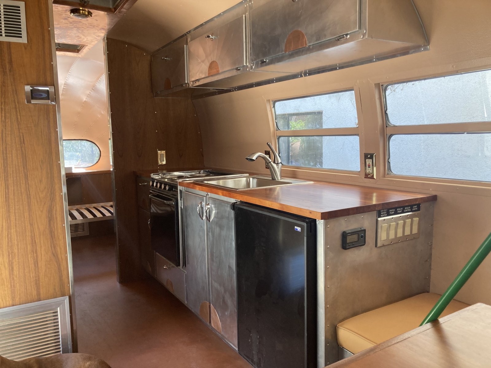
|
|
|
|
|
09-25-2022, 10:08 AM
|
#74
|
Rivet Master
2022 27' Globetrotter
DALLAS
, TX
Join Date: Apr 2022
Posts: 1,497
|
Quote:
Originally Posted by Jcondon
Luckily I made all of my cabinets and furniture out of aluminum. This saved enough weight to allow a dedicated negative conductor to each 12 volt load. |
Wow! Nice fabrication work Jcondon!! That really looks beautiful! And it's very unique as well.
|
|
|
|
|
09-25-2022, 10:28 AM
|
#75
|
4 Rivet Member
1949 22' Liner
1969 27' Overlander
1969 27' Overlander
Walnut Creek
, California
Join Date: Apr 2015
Posts: 325
|
Quote:
Originally Posted by foobar
Wow! Nice fabrication work Jcondon!! That really looks beautiful! And it's very unique as well.
|
Here is the other angle.

|
|
|
|
|
09-25-2022, 11:18 AM
|
#76
|
4 Rivet Member
1949 22' Liner
1969 27' Overlander
1969 27' Overlander
Walnut Creek
, California
Join Date: Apr 2015
Posts: 325
|
This is a photo of a 2023 Airstream battery box that someone posted today. This violates just about everything we talked about in this string. Don't do it like Airstream does it. Do it better. 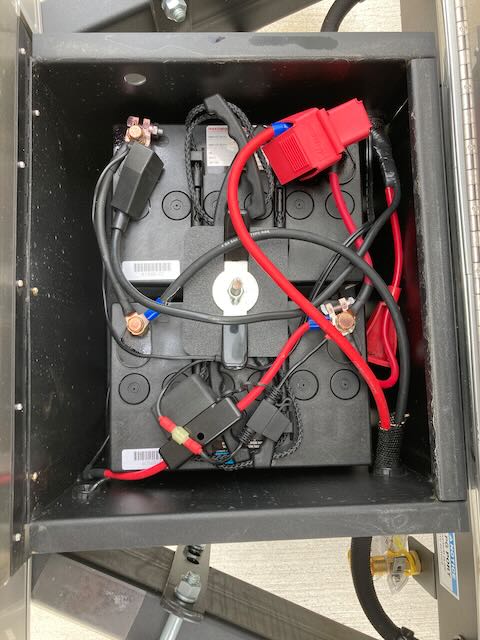
|
|
|
|
|
09-26-2022, 01:59 PM
|
#77
|
Rivet Master
1992 29' Excella
Virginia Beach
, Virginia
Join Date: Jul 2012
Posts: 747
|
Jcondon: That is some beautiful workmanship. You my friend are a metal work artist!
__________________
Pete
Virginia Beach, VA
1992 29' Excella Classic
TV 2006 Dodge Ram 2500
Mega Cab Diesel 4x4
|
|
|
|
|
09-26-2022, 02:07 PM
|
#78
|
Rivet Master
1992 29' Excella
Virginia Beach
, Virginia
Join Date: Jul 2012
Posts: 747
|
Quote:
Originally Posted by richard5933
Nothing really exotic happened. I reused the original threaded holes where they were in the correct place and still intact, and for those stripped out or in the wrong place I used rivnuts to mount. The front ones were mounted using a modified bracket on the inner end to put the connection point to the side of the cross member rather than the bottom of it. The situation with the inner workings being built minus the end caps has been left alone - they work fine, support the trailer well, and if properly cranked down we get no more rattles.
|
Quote:
Originally Posted by richard5933
|
I replaced mine as well, but I guess I got the original models as mine all have the supported rear bushing. The ones I replaced were not in great shape and the cranking extensions were too short, half the length they should be. That made them really difficult to reach. I'm guessing they were also replacements at one time. In my case, I had the benefit of a bare frame so I welded some specific mounting supports in place for the tail ends. I wasnt happy with the mounting situation on the crossmembers. As it was, It was too flimsy and only allowed one screw to secure it to thin sheet metal.
Quote:
Originally Posted by richard5933
If this was my build these two things might be the deciding factor between 12v and 24v, especially if the inverter was physically located further than a few feet from the batteries. Running an a/c from the inverter will push it towards the upper end of capacity for longer periods of time. Less impactful voltage drop is possible on 24v, as well as possible weight savings from the lighter weight conductors required.
|
Quote:
Originally Posted by richard5933
Even if the inverter is the only device running on 24v, it might be reason on its own to do so. Or it might not be.
|
Youve mentioned the importance of the distance of the inverter from the battery a few times and I apologize for not having bit on that. To be clear, I intend to use a hybrid inverter (Victron, probably) placed next to the battery bank. As close as possible. All of this will be in the front like yours is, but Ive removed the old battery boxes. Those are no longer in the way. (side note: They were partly responsible for the front end separation of my shell.) A previous owner removed the sofa, when they owned it. My plan is to build a bench seat dinette arrangement at the front with the area across the A frame under the windows holding the batteries, solar controller, hybrid inverter, breaker panels etc located there.
As for 24V or 12V still weighing it.
Quote:
Originally Posted by richard5933
First, there are some reasons to use the chassis/shell as the negative conductor. Weight reduction is one of them. It doesn't sound like much when we talk about the weight of one or two smaller wires, but on a trailer build all these ounces add up to pounds, and the pounds add up to substantial weight capacity being moved from the category of usable to cargo capacity to dead weight on the trailer.
|
Quote:
Originally Posted by richard5933
Some devices are designed to use the chassis as the negative conductor and make no provision for using a wire for this, like the tongue jack I'm using which gets its negative connection through its mount to the chassis.
Everything on a trailer has to be a balancing act. Yes, there is a real issue of electrolysis but I think that for the most part there are ways to deal with reducing this risk and that other issues can outweigh it.
|
My tongue jack works the same way (Its a Husky HB4500), thats it though, Ive made sure that everything Ive purchased so far has a negative as well as a positive pigtail.
[FONT=Arial]
Quote:
|
Originally Posted by richard5933;2632801My grounding/negative bonding solutions...[/FONT
The green grounding wires you saw in the photo all going to the common grounding bus are from the various devices which spec'd a separate grounding wire in their manuals. These include the inverter, converter/charger, solar charge controller, etc. It also serves as a bonding point for the negative side of the 12v breaker/fuse panel. There are some circuits in my trailer using the chassis as a ground, as this has been by Airstream for at least a few decades. Without opening up the inner wall panels there really is no way for me to retrofit all the circuits, and I'm not sure there would be any real gain in doing so.
In addition to the ground/negative connections to that common ground bus bar, there are a few more. The LP copper lines are bonded to the chassis near where the line is mounted, and the 120v breaker panel in the rear of the trailer has its own grounding lug on the chassis as close to the panel as possible. All of these were redone and then smeared with a good cover of electrician's grease to protect them.
|

I grabbed a link to your picture for illustration.
So, in your picture Im looking at the negative buss bar. Okay, thats easier to visualize.
__________________
Pete
Virginia Beach, VA
1992 29' Excella Classic
TV 2006 Dodge Ram 2500
Mega Cab Diesel 4x4
|
|
|
|
|
|
|
Currently Active Users Viewing This Thread: 1 (0 members and 1 guests)
|
|
|
 Posting Rules
|
You may not post new threads
You may not post replies
You may not post attachments
You may not edit your posts
HTML code is Off
|
|
|
|

 Recent Discussions
 |
|
|
|
|
|
|
|
|
|
|
|
|
|
|
|
|
|
|
|
|
|


 Linear Mode

