 |
|
 08-30-2017, 10:30 PM
|
#1
|
Rivet Master 
1958 26' Overlander
Battle Ground
, Washington
Join Date: Jun 2013
Posts: 871
|
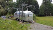
Our 1957-58 Overlander
We are in the process of a shell off on our Overlander. Purchased it in 2013, when I retired. The reason I labeled it as 1957-58 is the unit was first sold in September, 1957. The original warrenty copy is pasted on the wardrobe door and sale date was penciled in. It's titled as a 1958, but looking at the brocheres in the archives, we have a 1957 layout (toilet in the shower, left rear corner) not the 1958 layout.

Really didn't start on it until last year, just made it road worthy and repaired windows to keep the rain out.
We were fortunate, the interior was still original and complete. Just a few soft spots in the floor and a lot of wasps nest. The PO had left the trailer parked in his driveway in eastern Washington for 20+ years and never used it.
  
I won't bore you with all the teardown etc. that everyone goes through in a shell off. I will point out details in the reconstruction that I either borrowed from someone here on the forum or modified to meet our needs. More to come soon.
|

|

|


|
08-30-2017, 10:42 PM
|
#2
|
Rivet Master
1963 22' Safari
2020 27' Globetrotter
State of
, Washington
Join Date: Jul 2007
Posts: 2,512
|
Thanks for all your help! I look forward to seeing pictures of it coming back together! You are an amazing craftsman!
__________________
Scott & Megan
VAC LIBRARIAN WBCCI 8671
1963 Safari from the 1963-64 Around the World Caravan
|
|
|
|
|
08-31-2017, 10:55 AM
|
#3
|
Rivet Master
1958 26' Overlander
Battle Ground
, Washington
Join Date: Jun 2013
Posts: 871
|
Frame Changes
Before we took the shell off, I created patterns of the floor. Before doing this we had to decide on tanks and location so cross members could be moved/replaced to accomodate the tanks. We found the crossmember installation was very sloppy. Very few were 90 degrees to the frame rails. The distance from one crossmember to another could be off 1/2"-3/4" from side to side. Ended up replacing all but one crossmember from the axle back to square things up. I replaced with 2"X4" tubing to stiffin things up.

The patterns are an exact copy of the floor inside the channels. I also drilled 1/4" holes in the corners of each pattern over the frame rails. They acted as locating pins so I could set them back on the frame, in their original positions, later for another task.
I spent a lot of time trying to decide on what type of A frame for removing the shell. I always try to find multiple uses for anything like this and 12' high wooden A frames weren't of any use afterwards. I ran across an ad for pallet racks nearby. They were 12' wide and 12' high, perfect. These I could shorten and install in the barn for storage afterwards. I mounted them on some 2X12s to add a little stability and bought two HF 880' winches for the lift.
Once the shell was off, frame work started. I replaced the crossmembers as discussed above and started on a perimeter frame work. I wanted to get the floor separated from the frame/shell connection. I created a perimeter frame of 1.5"X1.5" tubing that would be welded to the outriggers/frame rails for the channel to mount to. I modified my car rotisserie to accomodate the longer trailer frame and mounted it up. Mounting it was simple at the rear I justed bolted it up to the cradle. At the front I welded a HF receiver to the cradle and just used the coupler.
This is after the frame was completed, sandblasted, and painted with POR15. The rotisserie makes the belly pan, floor installation, and tank mounting so much easier. Just spin it (once you have it in balance) to work right side up, sideways (great for welding), or up side down.
|
|
|
|
|
08-31-2017, 11:03 AM
|
#4
|
4 Rivet Member 
1957 26' Overlander
Winston Salem
, North Carolina
Join Date: Jan 2013
Posts: 467
|
Can't wait to see your progress!
|
|
|
|
|
09-02-2017, 11:29 PM
|
#5
|
Rivet Master
1958 26' Overlander
Battle Ground
, Washington
Join Date: Jun 2013
Posts: 871
|
Skinning the frame
Once the frame was completed I wanted to accomplish these things while the frame was on the rotisserie:
1. Create the belly pan, tank supports and access panels (tanks are spaced with one compartment between each tank so any plumbing; i.e grey to grey could be accomodated.
2. Install the sub-floor
3. Locate and install the tanks (1 bw, 2 grey, 1 fw)
4. Install electrical conduit in belly pan
5. Install the belly pan
Tank supports were easy except for the black water tank. I had picked up 4 4X8 sheets of 1/4" aluminum plate from a gentleman selling out his business to move to the east coast. It was a little heavier than I planned on, but at $50 dollars a sheet I couldn't pass it up. For the 1 fresh water and 2 grey water tanks it was simple. Just create a plate just short of the width of the outside of the frame rails and width was determined by covering 1/2 the width of each crossmember. All three are the 4" deep grey water tanks from VTS. These tanks are made of food grade material (verified with VTS) so they can be used for fresh water. The black water tank was a nightmare. I used the black water tank 1969-82 from VTS. The sloped bottom of this tank forced me to make the support from several pieces of aluminum plate to conform to the bottom of the tank. My TIG welder doesn't have the capacity for 1/4" plate so I farmed that out. If I had to do it over again, I'd do the same as Minno did and make the tank myself, with a simpler bottom shape. The hole in the support is for a hinged access panel to get to the valterra valves hidden in the compartment. More on that later.
This tank is 6-1/2" deep and is mounted at the rear of the frame. To minimize how much hung below the bottom of the frame, I added 1-1/2 square tubing over the top of the frame and crossmembers in the bathroom. Now I had 5-1/2" between the floor and bottom of the frame for this tank. I could live with 1" below the frame rails.
Access panels were made from .032 alclad, again just short of the width of the outside of the frame rails and width was determined by covering 1/2 the width of each crossmember.
All the tank supports and access panels are bolted on. The tank supports have 5/16" bolts and the access panels have #10 bolts. I drilled and inserted rivnuts in the frame rails and crossmembers for them. The tanks have an additional strap to hold them in place (6" wide strip of .032 alclad bolted to the frame rails) when you remove the tank supports, to give you access to any connections that have to be dealt with before you drop the tank out.
|
|
|
|
|
09-03-2017, 05:03 PM
|
#6
|
Rivet Master
1963 22' Safari
2020 27' Globetrotter
State of
, Washington
Join Date: Jul 2007
Posts: 2,512
|
Lots of forethought into your systems. I wish automakers thought future service through as much as you did!
__________________
Scott & Megan
VAC LIBRARIAN WBCCI 8671
1963 Safari from the 1963-64 Around the World Caravan
|
|
|
|
|
09-07-2017, 09:53 AM
|
#7
|
Rivet Master
1958 26' Overlander
Battle Ground
, Washington
Join Date: Jun 2013
Posts: 871
|
Installing the floor
I ended up using plywood 3/4" for the sub-floor. I used the patterns I created to cut them to size. Just some detail on the patterns. The front and rear end patterns ended up less than 48" front to back. The others are all 48" front to back to enable use of the factory finished sides of the plywood. I started at the rear. I knew I would be changing out the first crossmember forward of the rear crossmember to accommodate the size of the black water tank. Placing the second crossmember was determined after a lot of head scratching. I was planning on four tanks under the floor with access areas inbetween. From the rear:
Black Water; Access; Grey Water; Access; Grey Water; Access; Fresh Water.
The concern was making sure that the axle did not interfere with tank removal, plus all the sub-floor pieces,forward of the rear piece, would be 48" wide and these edges would land on the middle of a crossmember. As mentioned in an earlier post I ended up replacing all but one of the crossmembers to accomplish this. Also, the bottom of the stock crossmembers are not 2" wide so being able to drill and add rivnuts for the support and access panels would be a problem. I didn't want them to overlap.
So I ended up with 6 patterns; two end panels (different lengths front to back) and 4 standard patterns 48" wide front to back.
At the time, we were leaning towards installing either gue down marmoleum or cork. I was concerned about the sub-floor mating edges staying locked to each other, so one wouldn't lift in relation to its neighbor once the finished floor was installed. My solution was to route a slot in the mating edges 1/8" wide 9/16" deep. I installed an aluminum strip 1/8" thick 1" wide in the slot and epoxied it in place. I also routed the bottom edges with a 1/4" round over bit where the sub-floor is against the perimeter steel tube. This was to allow for any welds between the perimeter tube and the outriggers/frame rails that would interfere with the sub-floor sitting flush on the outriggers/frame rails.
I did one more thing before installing the sub-floor. On the top of the frame members that would contact the sub-floor I installed 5 mil polyethelene tape to act as a barrier between the two materials. Probably overkill, but I had the material because I also installed it on top of the steel perimeter tubing before I installed the aluminum channel. In doing research on reactions between dissimilar materials (aluminum/steel) I found this could be used as an 'insulator' so I spent a few bucks and bought some 2" and 3" wide rolls. When I put it on the 1-1/2" perimeter tubing I used the 3" and wrapped it around the inside of the tubing so the edge of the sub-floor wasn't in contact with the tube. It's a 3M product and almost like the VHB tape it doesn't want to come off once its made contact. It's called Ultra High Molecular Weight (UHMW) Polyethylene Tape. It's available in several thicknesses (mils).
Someone will ask so I'll throw this out; How did I seal the sub-floor. Not many will probably agree with this approach. I used a marine penetrating epoxy sealer. I sealed the top with two coats. I only sealed the outside 6" of each piece on the bottom. I am of the opinion you have to let the material breathe. It is bound to get moisture in it through spills, etc.. I did not insulate the belly pan (waste of time with all the tanks and plumbing). I'll add more info about the belly pan later.
|
|
|
|
|
09-09-2017, 02:13 PM
|
#8
|
Rivet Master
1958 26' Overlander
Battle Ground
, Washington
Join Date: Jun 2013
Posts: 871
|
Water drainage
I accept the idea that an airstream is going to leak. There are just too many joints, rivets, expansion/contraction, etc. that it will happen. Since I had already moved the sub-floor out of the shell/frame connection to reduce the chance of floor rot I started to look at what was a common issue discussed in the forums: leaks in the outer skin that allowed water to seep into the interior. If I can't stop them permanently, can I route the water out?
Not that I don't want to repair a leak, but if I can't get the water out, in a controlled manner, how can I 1) know the leak is happening and 2) find out before damage is done to the interior. Here is my solution; not perfect, but a step in the right direction.
Leaks in the shell will eventually put water down the wall and into the channel. Two issues here: Water collects in the channel. With the interior walls mounted to the outside of the channel, water will seep into the interior.
To deal with water in the channel I drilled a 3/8" hole down through the channel and perimeter frame tubing and inserted a 1/4" id plastic tube. The tube is flush with the bottom of the channel and extends below the bottom of the frame tubing. This minimizes water making contact with the steel.
Where to drill the holes required some thought. You have to visualize the structures involved. You have the wall ribs secured in the channels creating pockets around the perimeter. So a drain is need in each pocket.
For the interior walls I mounted the bottom edge inside the channel. It involved some trimming and will require some sealing around the ribs, but I think the theory is sound.
Now I have the water in the belly pan. How do I get it out? The belly pan is not completely water tight, but I wanted a known drainage point so it could be monitored, but it also has to be insect proof. I found a solution with a house product. A screened/louvered 1" diameter aluminum vent https://ventmastersstore.com/collect...-mill-bag-of-6
I took a 1" dimple die to form the hole. The dimple creates a small indent in the belly pan so the vent is the lowest spot. The ears on the bent were bent over and epoxied in place. After that set I epoxied the perimeter of the vent on the outside.
Like the drains in the channel I had to think about how the belly pan is compartmentalized by the outriggers/frame rails/crossmembers. My main concern is the portions of the belly pan that is permanently attached, not the support panels for the tanks or the access panels for the compartments between the tanks. Each one of these compartments needed a vent. I decided on mounting them at the rear of each compartment.
|
|
|
|
|
09-10-2017, 02:18 PM
|
#9
|
Rivet Master 
1966 26' Overlander
Woodstock
, Georgia
Join Date: Feb 2002
Posts: 8,525
|
great stuff here.....nice work and forethought
|
|
|
|
|
09-18-2017, 10:57 PM
|
#10
|
Rivet Master
1958 26' Overlander
Battle Ground
, Washington
Join Date: Jun 2013
Posts: 871
|
Tank Installation
Installing the 3 grey/freshwater tanks was pretty straight forward. Since I had installed the new cross members specifically for the tanks I kept the dimensions close to the tank size. I applied closed cell foam (adhesive backed) to locate the tanks (1/8" & 1/4" thick) to the frame members. A few had an additional piece of plywood to create the correct dimension.
In an earlier post on the floor templates I talked about drilling holes in each corner of the template over the frame rails to index the templates to the frame. By doing this, once I had the tank located I could place the template that corresponded to that tank and use the template to create a jig for drilling holes in the sub-floor for the fittings. In some cases the hole was in the existing template framework. In others that were inside the framework of the template I added an additional 'brace' with the hole located properly. To make sure the hole saw was well supported, each hole was a double thickness of plywood.
In most cases I drilled the hole about 1/2" larger than the fitting to allow for any minor movement of the tank or misalignment of the sub-floor. The template was then clamped over the matching sub-floor piece and the hole drilled with a hole saw. The template located the hole from the top side. I'd drill the hole part way through the plywood until the center drill bit was through the plywood. Then I would finish the hole from the bottom side. This kept the plywood from splintering on both sides of the plywood.
Once I had all the holes drilled I installed the sub-floor and bolted it to the frame. Keep In mind, I had raised the bathroom floor 1-1/2" to gain extra height for the black water tank. (rear bath) So that piece is bolted in by itself. The remained 5 pieces of sub-floor are encircled by the square tubing of the perimeter frame and splined to each other.
Holes in the floor for the black water tank will be done later as those fittings are in the side of the tank, not the top. Also, we haven't finalized the layout of the bathroom yet. We want to mock it up to make sure it all works, its a tight space.
|
|
|
|
|
09-19-2017, 12:22 PM
|
#11
|
Rivet Master
1958 26' Overlander
Battle Ground
, Washington
Join Date: Jun 2013
Posts: 871
|
Electrical Conduit
In renovating the Overlander one of the major changes is electrical. More complex systems with thermostats and control centers. Adding solar with all the control systems. Since one goal was to keep the interior looking as original as possible, I was concerned that all the wiring would require a lot of alterations to the original cabinets and walls. To minimize that I decided to bury as much of the wiring as I could in the belly pan.
To accomplish that I ran pvc conduit and boxes throughout the belly pan. Mainly on the curb side, since that was were I planned on placing most of the electrical controls. The street side had the majority of the plumbing so it seemed a good balance and minimized mixing water and electric. The boxes were mounted to be flush with the top of the sub-floor.
I made a template of the top of the box perimeter so I could take a router and rout the necessary holes in the sub-floor. Running the pvc pipe was tedious. The older AS have solid outriggers so I had to drill holes for each pipe and keep them in line. I used another template, so I could place the template on the outrigger and flush to the frame rail and drill pilot holes. That works great until you get towards the front where the frame rails are bent inward to create the tongue. The boxes were epoxied to the sub-floor and the conduit was epoxied to the boxes and outriggers.
All the boxes are underneath the beds or cabinets. In the front we are changing from the gaucho and free standing table to a wrap around banquette. So the only open floor, next to a wall, is a few inches on each side of the door and beneath the rear window in the bathroom. A false wall will be under the rear window for plumbing, so I had plenty of options for installing the boxes. There will still be short runs of wire above the sub-floor in certain areas, but a lot of it is hidden. This also allows future replacement of wiring to be a lot easier.
For wiring inside the walls/ceiling I ran aluminum fuel line (speedwaymotors.com) to fish wire through. They have three sizes so it works well. I just fastened it to ribs. Most of this wire is 12 to 16 gauge (all the lights are LED). The only wire not encased is the 2/0 cable from the inverter to the combiner box for the solar panels.
|
|
|
|
|
09-26-2017, 10:12 PM
|
#12
|
Rivet Master
1958 26' Overlander
Battle Ground
, Washington
Join Date: Jun 2013
Posts: 871
|
Outrigger end caps
When I removed the belly pan I noticed slots were worn through the belly pan where the ends of the outriggers make contact. The ends of the outriggers are just an edge. The mounting surface for the sub-floor and belly pan does not continue around the outer edge of the outrigger. I wanted to create an end cap to give the belly pan better support and make it from aluminum so any issues with dissimilar metals wouldn't affect the belly pan.
I started taking measurements on the outrigger ends and discovered the original ones and the new ones from AS do not have the same radius. (Mine are 4" high outriggers. The taller ones for newer frames may be identical??) I decided to match the smaller radius. This allows me to mount to the larger radius, but there is a slight gap.
Just to clarify all the outriggers are the same height. The ones with the smaller radiused end have a short bit of straight edge. The larger radius matches the height of the outrigger. The goal here is identical surfaces to bend and mount the belly pans over.
I decided to make the caps from bulkhead moulding from VTS. The mounting surface is approximately the same width as the mounting surface on the outrigger.

I modified the bulkhead moulding so I could create the radius. This is an extruded aluminum and quite stiff. I cut the pieces to length. On one end I cut the channel off the mounting surface for 1". This end gets riveted to my perimeter frame. (On a stock frame you'd mount it to the C channel.) On the other end I left about 3/4" of the channel in place. This would be slipped over the edge of the outrigger and riveted in place. In between the two ends I cut the channel down to 3/16" high to make the bend easier. Just to clarify the photo. You are looking at two caps, one on top of the other to create a better shot of the modifications.

To create the curve I mounted an old hole saw in my vise. I clamped one end of the piece to the hole saw and bent the piece around the hole saw. The narrowed channel of the piece is behind the hole saw, not on top of it. The piece will spring back some. I finished the radius by hand. Remember there are right and left outriggers so you will have to create some caps that are mirror images of the ones in these photos. You want the piece's mounting surface to match up with the outrigger mounting surfaces and the channel to fit over the end edge of the outrigger to hold it in place.

The flush end on mine are riveted to my perimeter frame, but the cap is countersunk and a countersunk rivet (aircraft) is used. The belly pan mounts over this so I didn't want a raised head creating a wear point. The other end with the full channel is mounted over the outrigger edge and riveted in place. I mounted the full channel end first so it is flush with the outrigger mounting surface and let the flush end wrap around.

The photos in my prior entry on electrical conduit installation shows a more complete picture of the caps in place.
|
|
|
|
|
10-01-2017, 11:44 AM
|
#13
|
Rivet Master
1958 26' Overlander
Battle Ground
, Washington
Join Date: Jun 2013
Posts: 871
|
Entry Stairs
(In case you saw the earlier post on this, I deleted it. The photos didn't upload correctly.)
The original stair was in sad shape, guides worn out supports rusted pretty bad. When I replaced the original axle I went from a dropped to a straight axle. That added about 4" in height. My oversized tires (compared to the stock 16.5" split rims & tires) raised it another inch. I had the leaf springs rebuilt and rearched, add another inch. Decided to go to a 2 step replacement. I wanted something with more stability than you get with most, especially if you haven't put down stabilizers.
You may have noticed on the photos of my electrical conduit there is some frame work sticking out from the belly pan. That's the mounting area for the entry stairs. (frame's upsidedown on my rotisserie).

I decided on a unit from TorkLift.
https://www.etrailer.com/RV-and-Camp...t/TLA8002.html
It's all aluminum and the legs on the lower step are adjustable for height and the pads are hinged. The mounting frame has 2 stops for height adjustment so its quite versatile. There is a down side: folded up its taller than my 4" frame.
 
I also wanted to enclose the steps when not in use to keep pests out and keep them clean while traveling. I've added the rear and side panels and will make a cover out of .032. I plan on hinging it at the back and latches on the front. I may have to modify the bottom of the door for this, we'll see. The door's been partially reskinned and not very well.

My ground clearance to the belly pan is 18" and to the bottom of the step enclosure is 10". I'll just have to be careful.
|
|
|
|
|
10-06-2017, 09:16 AM
|
#14
|
Rivet Master
1958 26' Overlander
Battle Ground
, Washington
Join Date: Jun 2013
Posts: 871
|
Waste water plumbing
I decided to try something different for the black/grey water tank drains. First off, I came to this project as a bit of a car nut. I am in the middle of a restro rod 61 Tbird. Keep it looking stock, but get all the modern pieces in place and sort of hidden. That's the same approach I took for the AS. To my 'artistic' side putting all the drain lines below the belly pan was out of the question. I was willing to compromise the ability to completely drain the tanks for the look. Getting 3 waste tanks (1 black & 2 grey) drained led to some crazy ideas. The one I settled on is still crazy, but I decided I wanted the challenge of making it work.
Remember I have the tanks spaced out back to front: black water, access bay, grey water rear, access bay, grey water front. The front grey water is connected to the kitchen sink. The rear grey water is connected to the bath tub. The toilet and bath sink connect to the black water tank.
Connecting the two grey water tanks together was simply a matter of putting holes in crossmembers to connect the two tanks together with a 1-1/2" line as close to the bottom of the tanks as possible. To keep water from moving back and forth between these tanks while traveling, I will have a valve in the line. The rear grey water tank has a second outlet on the rear face to drain both when needed.
This is where the complicated part begins (OK to some crazy is more appropriate). After reading the forums for an extended period, one topic comes up frequently: flushing the black water tank. The wand was out as I will be using a macerating toilet and the back-washing technique from the drain elbow doesn't appear very effective. The spinning fresh water flush has mixed reviews.
I decided I wanted to try using the grey water discharge to flush the black water tank. Since the black water drain line and tank low point are off center to the street side I put the grey water inlet to the black water tank towards the curb side to try and create some turbulence. That was the simple part. Just draining the grey water by gravity didn't seem powerful enough, so I added a macerating pump to the design. Not only would it create more turbulence, but would speed up the discharge process (in case I'm at the dump station and people are lined up behind me.) Just to keep things difficult, I also wanted to be able to drain the grey water tanks separately. I could see where an extended stay somewhere could make this preferable, we'll see. After three mockups here is what is now in the access bay between the black water and rear grey water tank. Keep in mind this is up-side-down. The bench surface represents the sub-floor.

The portion circled in green is in the access bay. In the upper right (purple circle) is the discharge from the rear grey water tank. It connects to the macerating pump (pink circle) The pumps sends water to the wye pipe which splits the flow to two valves (blue circles). The top valve directs water into the curb side of the black water tank. The bottom valve directs water to the bypass, around the black water tank, to the discharge line at the rear crossmember. There are several rubber connectors in the 1-1/2" lines to allow for misalignment and any movement of the tanks/lines while traveling. The easiest ones to spot are on the bypass line at the bottom of the picture: a straight connector at the bottom left corner of the black water tank, and a 90 elbow at the other end of the bypass line at the lower right corner of the picture.
The area in orange is in the black water tank bay. The two blue rectangles represent the access door in the black water tank support plate. A picture of the support plate is in the 'skinning the frame' entry.
The door gives you access to the valve handles for the (1) black water tank valve, (2) grey water to black water tank valve, and (3) grey water bypass valve to the discharge line
 

In the last photo you can see a portion of handle #1 inside the access opening.
|
|
|
|
|
10-10-2017, 11:06 AM
|
#15
|
Rivet Master
1966 26' Overlander
Woodstock
, Georgia
Join Date: Feb 2002
Posts: 8,525
|
awesome work there
|
|
|
|
|
10-11-2017, 04:41 PM
|
#16
|
Rivet Master
1958 26' Overlander
Battle Ground
, Washington
Join Date: Jun 2013
Posts: 871
|
Modified Tank Support
I went back and made a change to the front grey water tank support. It's made from 1/4" aluminum plate that I picked up. This tank is located from the axle tube back past the rear spring eyelet. I hit a snag with it and had to modify it for ease of removal. It was hanging up on the spring eyelet bolt and I was afraid I damaged the brake lines (I have hydraulic disk brakes). What I did was cut it in half from front to rear.

The tank support had to be double notched. The large notch is for the spring eyelet welded to the bottom of the frame. The smalled inside notch (with a layer of foam rubber over it) is to slide past the leaf spring rear eyelet bolt.

To get ready for the cut I made my support brace, another piece of 1/4" plate 3-1/2" wide X 24" long. Drilled pilot holes in the brace, then centered it over where the splice would be, clamped it in place. Using the pilot holes in the brace as a guide I drilled pilot holes in the support piece. I tapped the support piece for 10-24 bolts. Drilled the support brace to clear the 10-24 bolts and then cut the support in two.
My objective was to use the support brace holes to keep the original dimensions of the tank support by establishing the hole spacing first. The slot is just the wide of the saw kerf ~ 1/8". The support bolts into two crossmembers and the frame rails so this center brace doesn't really take a lot of load.

On the inside I ground off the ends of the bolts flush with the support surface so they wouldn't create wear spots on the tank. I also added 1/8" foam rubber to take up some slack in the tank enclosure. I only covered the edges to try and get the tank bottoms to flatten out. They tend to be concave from the factory.

|
|
|
|
|
10-11-2017, 07:43 PM
|
#17
|
Rivet Master
1986 34' Limited
1975 27' Overlander
1969 21' Globetrotter
Conifer
, Colorado
Join Date: Jun 2009
Posts: 8,317
|
Very creative. Newer Airstreams are rather difficult to access things like underfloor tanks and plumbing. You have to drop pans and tanks to get at some of the fresh water plumbing. Your trailer will be much easier to work on should a problem arise.
Very nice...
David
|
|
|
|
|
04-27-2018, 10:53 PM
|
#18
|
Rivet Master
1958 26' Overlander
Battle Ground
, Washington
Join Date: Jun 2013
Posts: 871
|
Bulkhead wall connection
Been a while since I posted anything. Guess I better start catching up. Worked on the trailer most of the winter. Had to do a little renovation. When our rainy Fall got going I found a few leaks so I dismantled the bit of interior we had in place and re-sealed everything. Changed out some of the insulation that I wasn't happy with and put in 1" foil backed R-Tech on the walls/ceiling & 1-1/2" Owens Corning Formular in the end caps. Once that was done, back in with the interior walls. I'll talk more on insulating the end caps when I show you the aluminum end cap I did.
I wanted to use the bulkhead wall moldings from VTS to secure the interior walls. When I tried one last summer I found bending the molding was a problem as the extruded aluminum is very rigid. It tended to bow sideways. Probably because channel is on one side, not the middle. This time I decided mods were needed to make the pieces more pliable so they would fit the wall snugly and then I could reshape the plywood wall edge to match the shape. We're using the original plywood walls. They never closely match the wall shape.

To make the moulding flexible I cut kerfs in the channel walls, without cutting the mounting flange. My miter saw has an adjustable stop for the depth of cut, which makes the process a lot faster. I decided to cut the kerfs with a 3/4" space in between. I probably could have gone farther apart, 1" or 1-1/4".

I made a jig to cut these so I wouldn't have to lay out all the cuts. I used the miter saw to cut to slots in a 1" square tube that was big enough to slide a 1/8" X 1/2" X 2" piece of metal in perpendicular to the tube as a stop and epoxied it in place. By using a piece only 1/2" wide for the stop it sits above the deck of the saw and the mounting flange can slid under the stop.

Clamped the jig to the miter saw to the right of the blade for a 3/4" gap and clamped a second piece of the square tubing to the left side. Moving the moulding away from the fence placed the channel on the mounding at the low point of the saw blade (Channel is facing you, not against the jig). Just set the end of the mounding against the jig stop, make your first cut, slide the new cut into the jig stop and keep going, over and over again. Drilled holes for rivets in the mounting flange so they lined up with the middle of the uncut channel every few inches.

Couple of notes: The boss is OK with the slots in the molding. If she changes her mind I'll find some automotive trim tape or moulding to cover up the exposed side. On the wall shot you'll see a gap in the molding about half way up. A wooden shelf goes there and will cover the gap.
|
|
|
|
|
06-25-2018, 10:09 AM
|
#19
|
Rivet Master
1958 26' Overlander
Battle Ground
, Washington
Join Date: Jun 2013
Posts: 871
|
Table Pedestal
Just passed this info on to someone else and thought I should get it added to this thread.
We are putting in a banquette to replace the gaucho and separate dining table. The street side will extend to the stove on the street side and go just short of the door on the curb side (kind of an upsidedown J). The boss wanted the extended street side so she can be away from the table top while knitting, etc..
I wanted the table pedestal to be more versatile than just up/down to make the spare bed. I found one that you can 'unlock' the table top and slide it in several directions. That appealed to me. The wife can slide it towards her and keep the wine close at hand.
The hard part was finding a dealer to sell me the unit. Its made in Europe. I found an RV parts dealer in France that was willing to ship to the US.
The table top in the photos was to test the table top lock. Its about 20" X 16".

Top in the centered position.

Top slid max to the side. It will slide in both directions.

Top slid max to the back. It will also slide forward.

Top will also rotate about 35 degrees either direction. The handle on the table top is to unlock the pedestal for height. You mount it on the underside of the table top.
Here's the website.
https://www.mecatechnic.com/fr-FR/pi...mm_CQ10184.htm
They will give you a quote for freight before ordering. Surprisingly,
my freight was only 38 Euros. They shipped with TNT Freight, which is owned by FedEx. It only took about 3 weeks to arrive.
They currently have the same unit with a round pedestal on sale. I believe it may rotate more than the oval base I bought, but the ad doesn't specify.
https://www.mecatechnic.com/fr-FR/pi...mm_CQ10339.htm
I would make one recommendation if you get this unit. The lock cable where it comes out of the pedestal has a strap to position it. Remove the strap and let it come out perpendicular from the base. Re-position the strap on your table top. The cable works better if it has 'gentle' curves. the factory retainer is very close to the end of the cable and I believe it puts strain on the cable.
|
|
|
|
|
07-27-2018, 07:41 AM
|
#20
|
Rivet Master
1956 22' Caravanner
Don Pedro Island
, Florida
Join Date: Apr 2013
Posts: 613
|
Thats cool...I like it!
|
|
|
|
|
|
|
Currently Active Users Viewing This Thread: 1 (0 members and 1 guests)
|
|
|
 Posting Rules
|
You may not post new threads
You may not post replies
You may not post attachments
You may not edit your posts
HTML code is Off
|
|
|
|

 Recent Discussions
 |
|
|
|
|
|
|
|
|
|
|
|
|
|
|
|
|
|
|
|
|
|


 Linear Mode

